Logic Gates
Circuits to Truth Tables
Circuits to Expressions
Expressions to Circuits
Finding SOP from K-Map
Finding POS from K-Map
Finding SOP from K-Map having Don't Care
Half Adders
Full Adders
Flip Flop
Integrated Circuits
Decoders
Multiplexers
Registers
Counters
RAM
ROM
Number Systems
Complements
Number Representations
Binary Addition and Subtraction
Gray Codes
Error Detection Codes
Register Transfer Language
Bus and Memory Transfers
Arithmetic Micro-operations
Logical Micro-operations
Shift Micro-operations
Basic Computer Organization
Timing and Control
Instruction Cycle
Instruction Types
Interrupt Cycle
Complete Computer Description
General Register Organization
Stack Organization
Evaluation of Arithmetic Operations
Address Modes
Instruction Formats
RISC and CISC Architectures
Parallel Processing
Multiplication Algorithms
Genaral Register Organization
In a CPU, some registers are very specific to their task, hence they are used very frequently by the control unit. Some anonymous registers are also used and operations of theses registers are subject to the need and type of information stored in them. Following is an organization of these registers in a CPU:
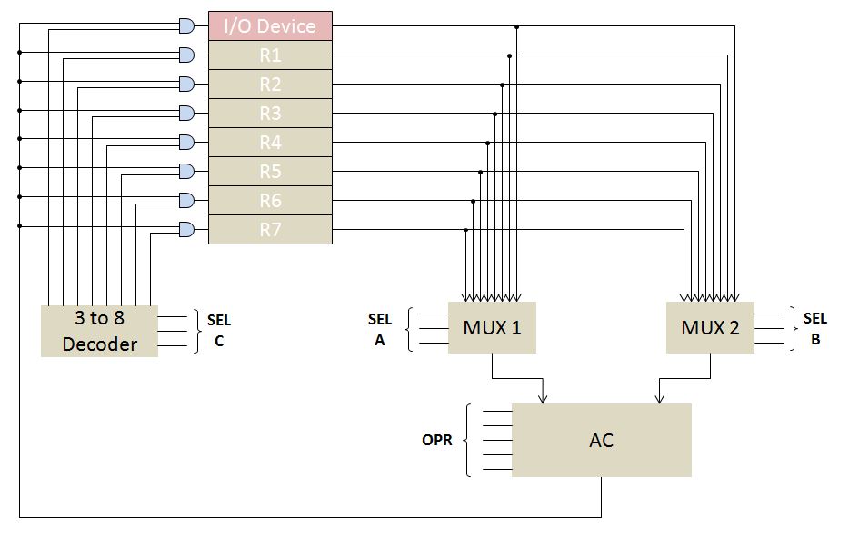
As the diagram depicts, a block of seven registers is used for storing anonymous data. Two multiplexers of 8 to 1 size are used to extract the contents of two registers at a time. Here MUXes are of 8 to 1 size because we have another line for I/O devices along with seven registers. The two extracted values are processed in AC with the help of ALU. Here to specify the appropriate operation, five lines of OPR input are used. The computed output is then ANDed with the outputs of a 3 to 8 decoder. Since a decoder activates only one output line at a time, the computed output goes in only one register. The appropriate destination register is specified by the 3 input lines of decoder.
Control Word
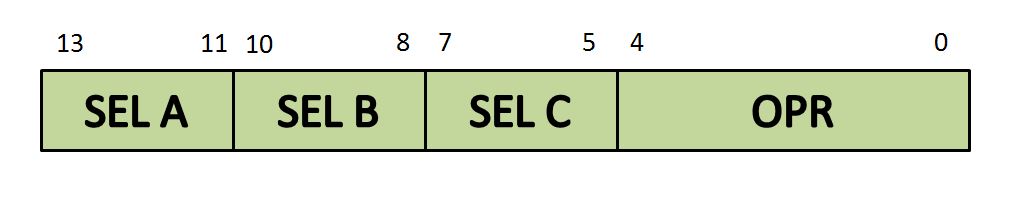
A control word is a binary information that makes the general register organization happen. It is basically a 4-part binary code consisting of SEL A, SEL B, SEL C and OPR Inputs in the general register organization diagram. The control word is as follows:
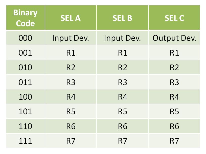
All the possible combinations of a control word and their respective selections are concluded in the following table:
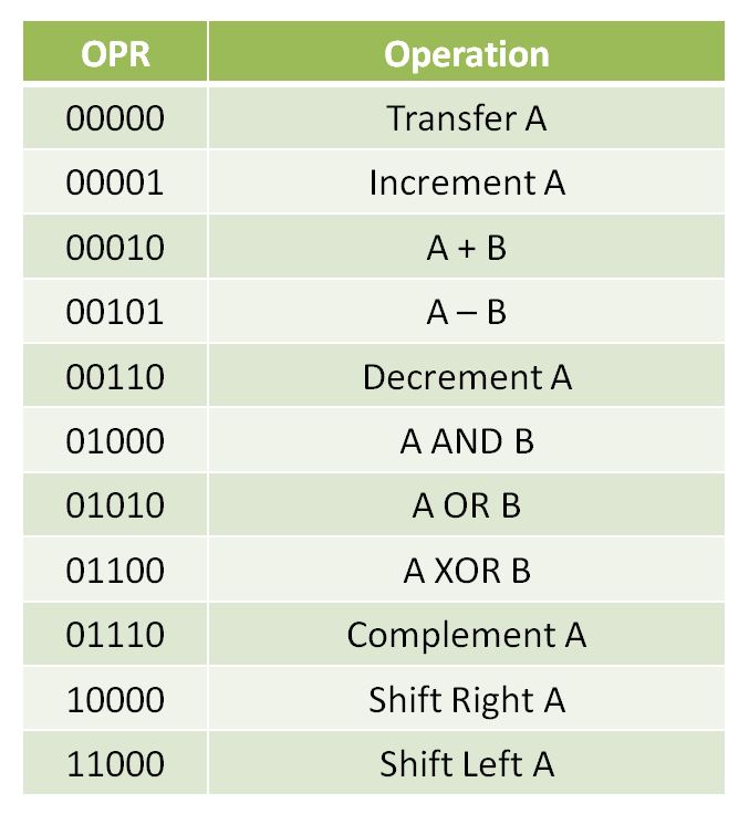
In the control word, since we know that the OPR is a 5 bit information, it can denote a total of 25 operations. But here we conclude only 11 important operations.